Process Engineering · Advanced Fibers · Applied R&Dinfo@epcotec.de
EPCOTEC
EN/DE

NANOFIBER PROCESS ENGINEERING

From material formulation to controlled nanofiber production.

EPCOTEC develops the complete route from polymer, solvent or melt formulation to a repeatable nanofiber product. Laboratory equipment, pilot systems and continuous production concepts combine controlled dosing, high voltage, airflow, climate, collection, web transport, solvent management and quality verification in one engineered process.

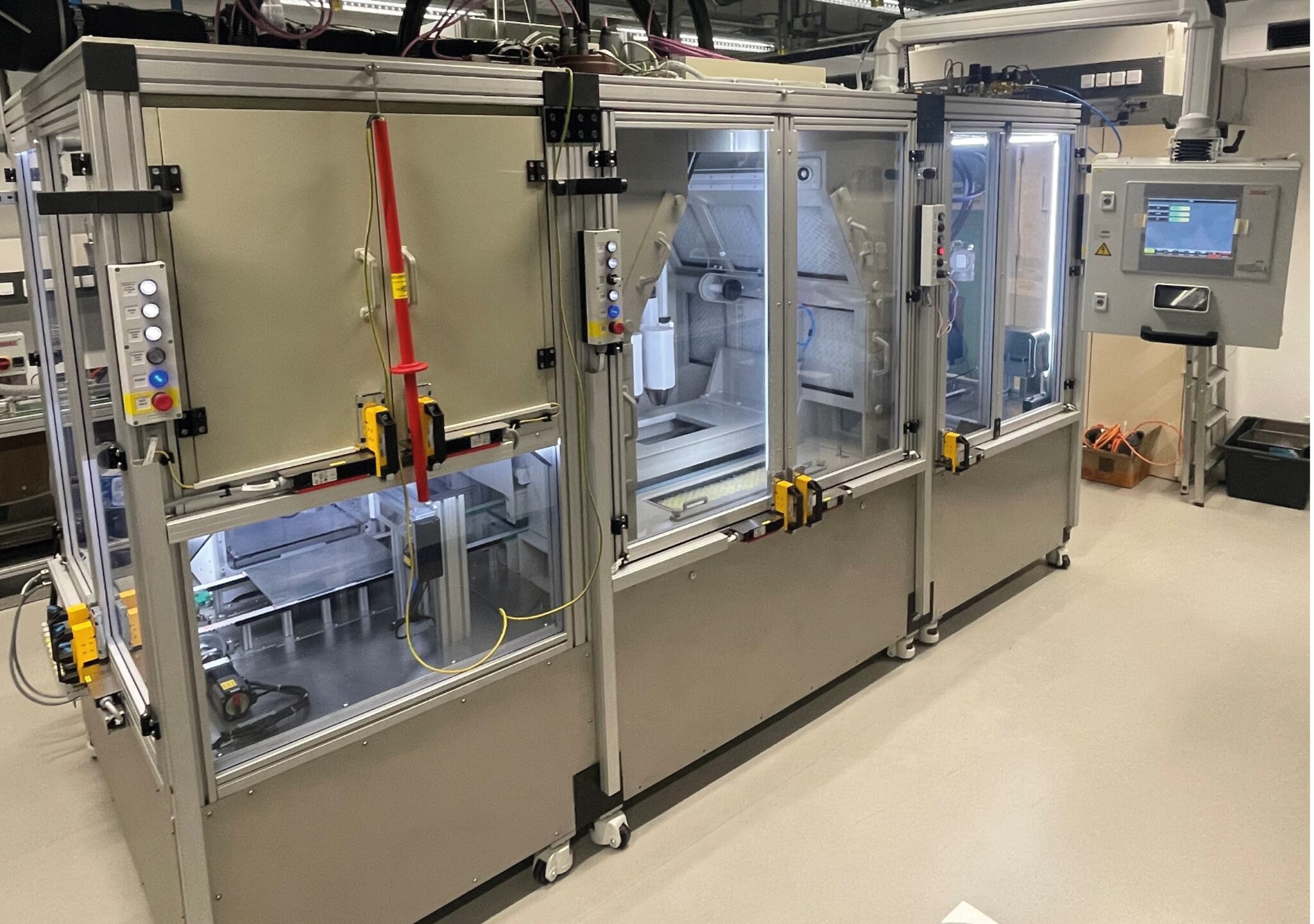
EPCOTEC ESPIN enclosed nanofiber production system

PROCESS FUNDAMENTALS

Nanofiber quality is created by the complete process window.

Fiber diameter alone does not define a successful nanofiber product. Molecular weight, polymer concentration, solvent volatility, conductivity, surface tension and viscosity interact with voltage, flow rate, spinning distance, temperature, humidity and airflow. Collector geometry and substrate movement then determine orientation, layer uniformity, adhesion and pore structure.

EPCOTEC begins with the required product function—such as filtration efficiency, pressure drop, release profile, scaffold porosity, barrier performance, basis weight or mechanical reinforcement. That target is converted into measurable material properties and a documented operating window. Laboratory trials establish feasibility, the pilot confirms repeatability and continuous handling, and production engineering translates the evidence into safe, maintainable machinery.

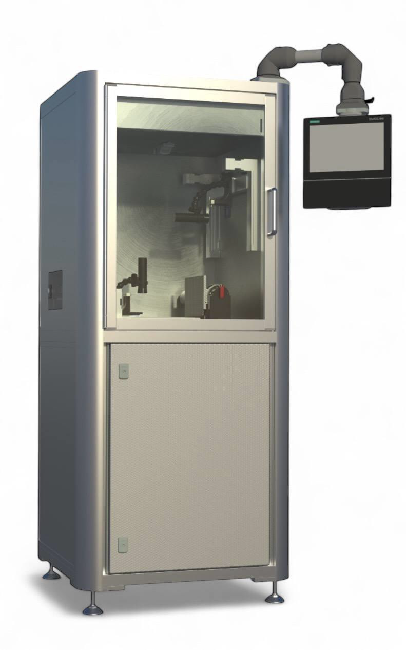
Enclosed continuous pilot nanofiber line

PILOT PROCESS PLATFORM

Before choosing a spinning method, prove the entire material path.

A representative pilot must reproduce more than the spinning head. It must control formulation preparation, dosing stability, climate, electrostatic field, air distribution, substrate transport, collection distance, exhaust and safe operator access. Longer trials reveal effects that short laboratory samples cannot show: drift in viscosity, deposit buildup, cleaning intervals, edge-to-edge variation and interaction with the carrier web.

The pilot therefore becomes the evidence base for method selection and scale-up. It identifies the practical operating envelope, produces customer samples and supplies the mass, energy, safety and quality data needed to define the industrial line.

SPINNING METHODS

Choose the fiber-forming principle around the material, product and required scale.

Needle-based electrospinning
01

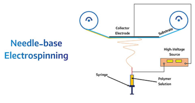
Needle-based electrospinning

A precisely metered polymer solution or melt is delivered through one or more capillaries. The electric field forms a Taylor cone and draws a charged jet that thins before reaching the moving collector.

Typical fitFlexible formulation development, accurate dosing, coaxial trials and research-scale process mapping.
Needleless electrospinning
02

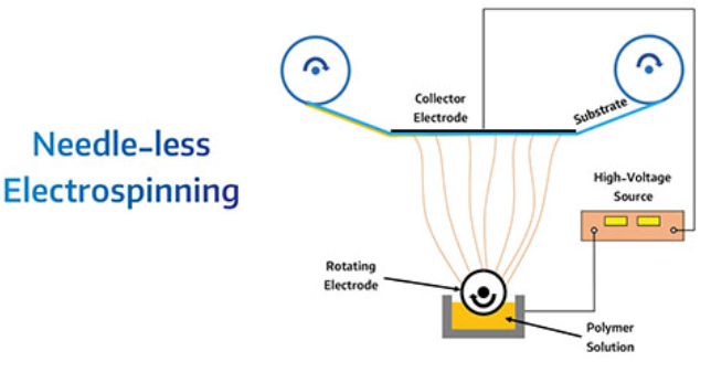
Needleless electrospinning

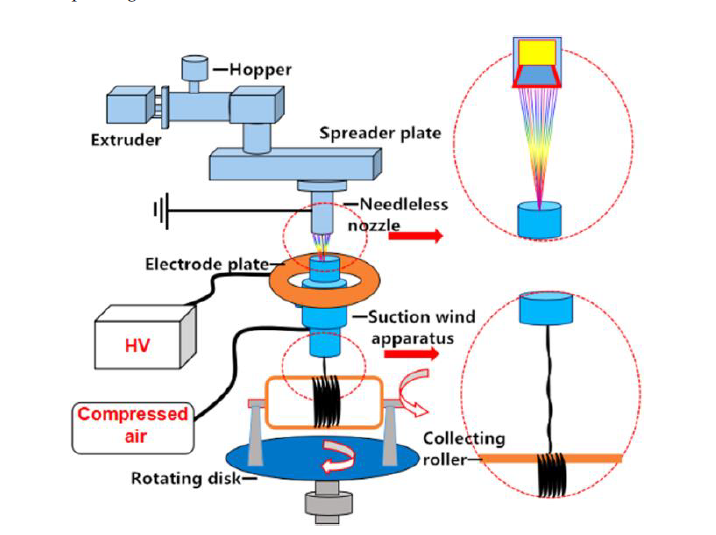
Multiple jets are generated from a free liquid surface or rotating electrode. The method avoids large needle arrays and increases active spinning area while simplifying blockage and cleaning management.

Typical fitContinuous coating, wider substrates and industrial productivity after a stable formulation window is established.
Centrifugal spinning
03

Centrifugal spinning

A rotating head uses centrifugal force to eject and attenuate polymer streams. Head geometry, rotational speed, viscosity, temperature and controlled air determine fiber formation and deposition.

Typical fitHigh mass output, thicker nanofiber or microfibre layers and robust industrial substrates.
Blowing-assisted spinning
04

Blowing-assisted spinning

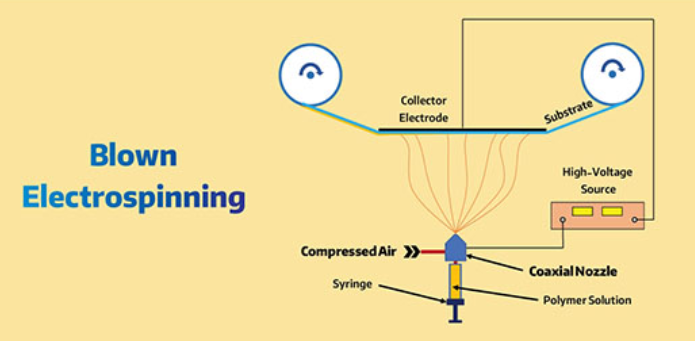
Compressed gas stretches and transports the polymer jet. Airflow raises throughput and can be combined with electrostatic forces to improve jet stability, collection efficiency and web uniformity.

Typical fitScale-up, three-dimensional structures and formulations requiring higher deposition rates.
Melt electrospinning
05

Melt electrospinning

A thermoplastic melt replaces the solvent system. Temperature, melt viscosity, nozzle design, electrical field and collector motion are coordinated to create stable fibers and defined structures.

Typical fitSolvent-free processing, recyclable thermoplastics, controlled meshes and structured medical scaffolds.
Coaxial & emulsion spinning
06

Coaxial & emulsion spinning

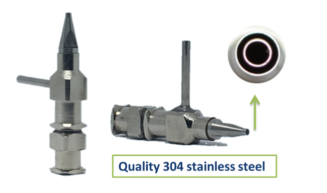
Concentric feeds or multiphase formulations create core-shell fibers. Sensitive active compounds can be protected inside the fiber and released by diffusion, degradation or an external stimulus.

Typical fitDrug delivery, wound care, encapsulation and multifunctional filtration media.

SCALE-UP ARCHITECTURE

From one stable spinning zone to a complete production site.

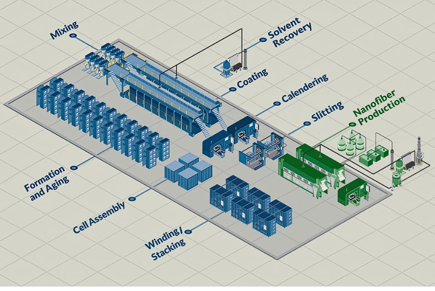
Scale-up is not achieved simply by multiplying nozzles. Throughput, working width, electric-field distribution, air balance, solvent load, residence time and substrate control must develop together. EPCOTEC uses pilot measurements to determine the number and arrangement of spinning zones, independent dosing circuits, collection geometry and online controls.

The production concept can include raw-material preparation, mixing and filtration, climate-controlled spinning rooms, multi-head deposition, continuous unwinding and winding, coating or lamination, slitting, ageing, solvent recovery, exhaust treatment and quality data management. Interfaces to utilities, building layout, safety zoning and downstream assembly are defined before the final industrial design.

LaboratoryFormulation screening, jet stability, microscopy and functional samples
PilotContinuous substrate trials, uniformity mapping and extended operating runs
ProductionWorking width, multi-zone output, automation, safety and maintainability
Integrated industrial nanofiber production site concept

APPLICATION ENGINEERING

Six application fields developed from measurable performance requirements.

Air & liquid filtration
01

Air & liquid filtration

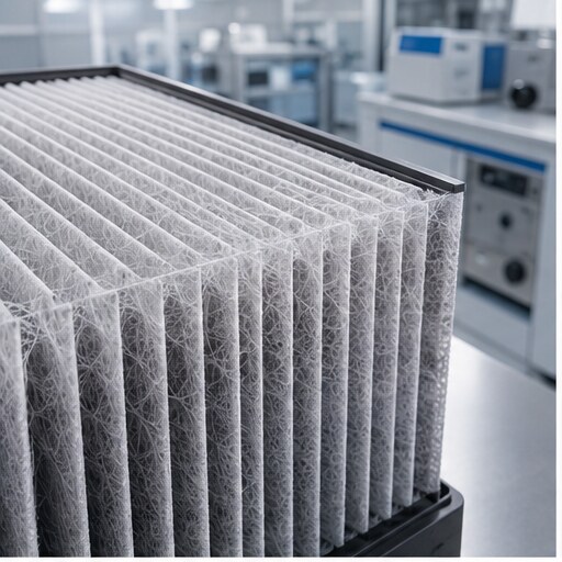
Fine fibers provide high specific surface area and controllable pore structures at very low coating weight. EPCOTEC develops the nanofiber layer together with the carrier substrate, bonding concept and web handling so filtration efficiency, pressure drop, durability and cleanability remain balanced.

Medical scaffolds
02

Medical scaffolds

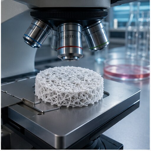
Nanofiber morphology can reproduce important structural characteristics of extracellular matrices. Polymer choice, fiber diameter, orientation, porosity, degradation, mechanical behavior and sterilization compatibility are developed around the target cell and tissue response.

Drug delivery & patches
03

Drug delivery & patches

Active ingredients may be dispersed in a fiber, encapsulated in a core-shell structure or combined with a functional carrier layer. Release profile, dose uniformity, residual solvent, skin contact, packaging and reproducible production are treated as one development program.

Protective textiles
04

Protective textiles

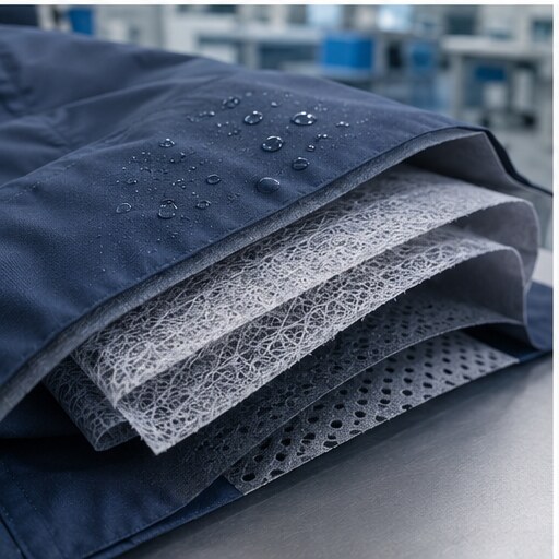
A thin nanofiber membrane can add aerosol capture, liquid resistance, breathability or chemical functionality to an existing textile. The coating must survive flexing, lamination, wear and the intended cleaning or disposal route without losing its protective function.

Energy materials
05

Energy materials

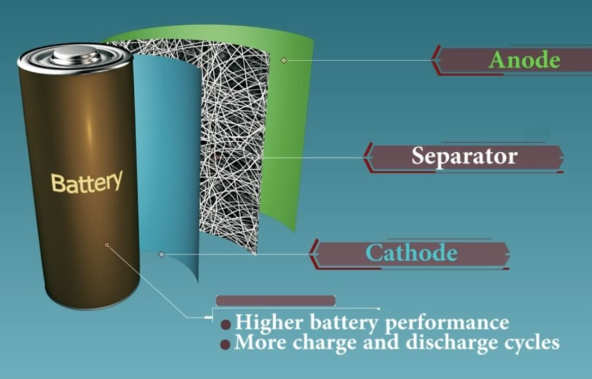
Porous fiber webs can support battery separators, electrodes, catalysts and fuel-cell components. Controlled thickness, surface area, wetting, ion transport, thermal stability and compatibility with downstream assembly guide both material recipe and machine architecture.

Functional coatings
06

Functional coatings

Nanofibers can carry adsorbents, catalysts, antimicrobial agents, sensors or optical functions. EPCOTEC integrates deposition on roll goods, membranes and selected three-dimensional components with controlled climate, exhaust, curing and quality verification.

METHOD COMPARISON

Technology selection matrix

The appropriate spinning principle depends on formulation, fiber architecture, target output and end use. This matrix supports an initial method selection; the final configuration is confirmed through controlled laboratory and pilot trials.

MethodTypical productivityFiber controlSolvent-free optionBest scale-up use
Needle electrospinningLow to mediumVery highMelt variantR&D, coaxial fibers and precision dosing
Needleless electrospinningMedium to highHighLimitedWide and continuous nanofiber webs
Centrifugal spinningHighMedium to highPossibleHigh mass output and robust coating
Blowing-assisted spinningHighMediumProcess dependent3D structures and higher-throughput scale-up
Melt electrospinningLow to mediumVery highYesStructured scaffolds and controlled meshes

Indicative comparison. Actual output and fiber quality depend on the polymer system, working width, basis weight and validated process window.

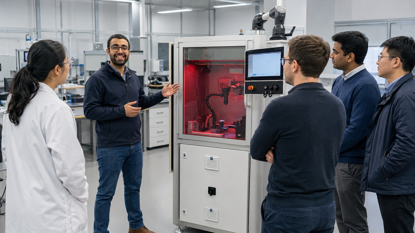
EPCOTEC engineer explaining the nanofiber system to technical visitors

DISCUSS YOUR NANOFIBER PROJECT

Bring us the material, the target function and the required production scale.

A useful first discussion starts with the polymer or raw material, available solvent or melt route, intended substrate, target fiber structure, required performance and estimated capacity. EPCOTEC can then define the most efficient next step—from formulation screening and a focused laboratory trial to a representative pilot campaign and industrial scale-up concept.

Discuss a nanofiber project